2D Design and Cutting
This week, we learned how to use the Arduino IDE and Fusion 360 to program and power circuits and to design 2D objects respectively. To get started with Fusion 360, I followed a tutorial from the course page, where I learned how to select multiple elements and set their parameters using the shortcut CNTRL keys. With these quick shortcuts alongside the overview from lab this week, I am ready to begin designing my press fit construction kit.
For my press-fit kit, I knew I wanted to design an object and build parts around it, so I decided to build a sort of vase or cup. This cup will be built with rotating square walls made of the two pieces at the top of my sketch. I also included a design for the base piece and the base layer wall at the bottom of my sketch. Because I am trying to press fit with non-ninety-degree angled connections, I am going to have to design and measure my notches to sit at the correct angle for comfortably placing my rotating rectangles, which I think will be my biggest obstacle. I've also noticed that the notches I have sketched are extremely large in comparison with the piece size, so I plan to make the shapes bigger while shrinking the notch size for a cleaner finish.
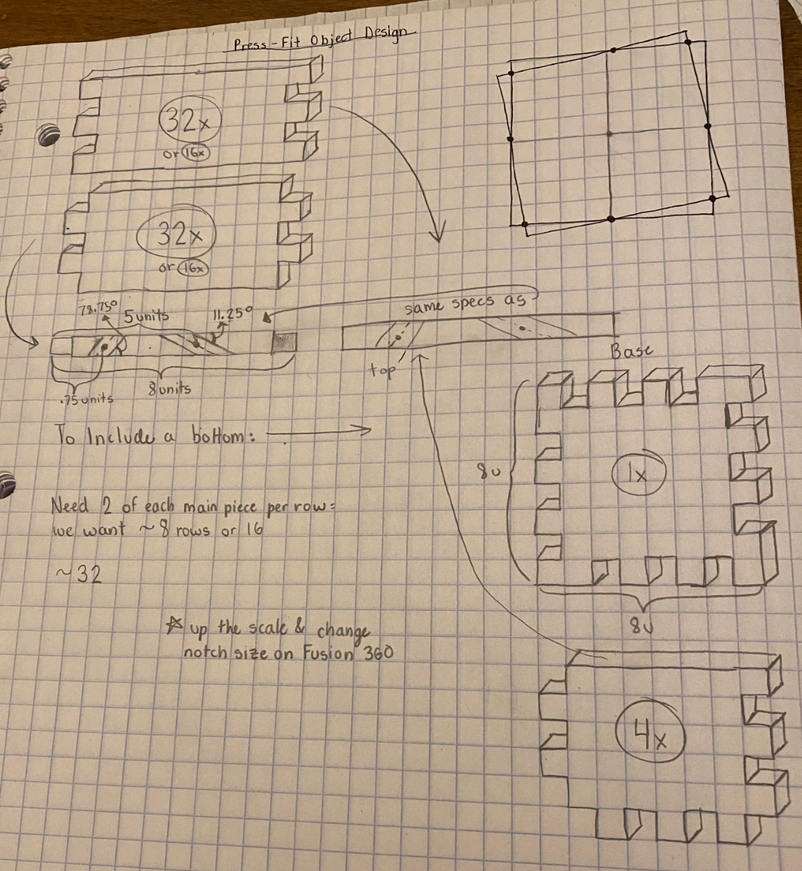
With this idea in mind, I booted up Fusion 360 and began creating my shapes on the computer. The base of my square cup was pretty straightforward to design. I built a square base with evenly spaced notches around the perimeter in the same pattern as my drawing. I decided to make my notches as deep as the cardboard was thick. This way, when I add pieces vertically, the tabs won't stick out of the sides. I'm just hoping that the notches are big enough to print nicely on Sunday!
The wall pieces were a bit more interesting. To get this rotating effect, I am trying to design notches with a bit of an angle in their cut. I am not exactly sure how to do this, as the notch diagonal requries a change in the z. Can the laser cut at different depths to achieve this shape? With these questions in mind, my first task was to 3D model the entire base wall shape from my drawing. The straight-edged sides were pretty straightforward, and I just added lines in my sketch to mark where my straight notches would go. To get started on these diagonal notches, I am first going to add points on the 2D sketch border to denote the center of the notch at the front of the object face.
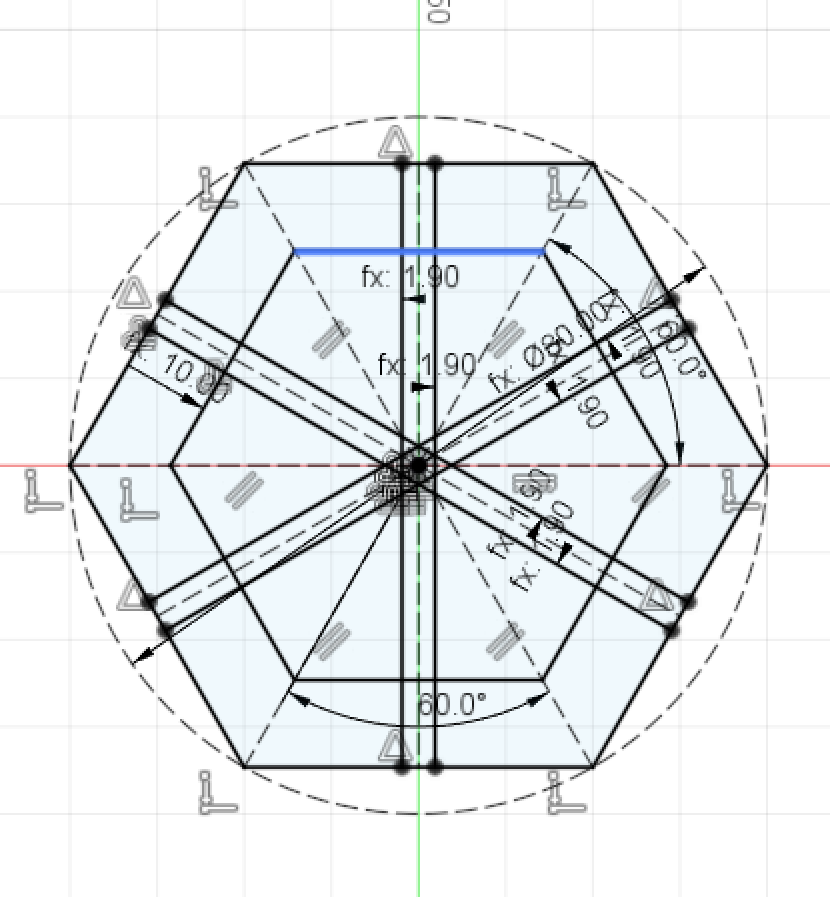
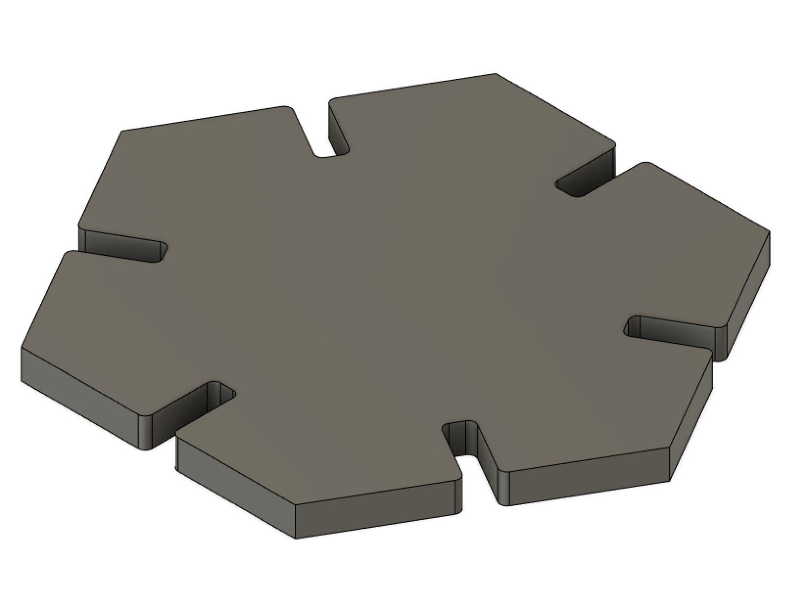
Thinking about the problem a little more, I realized that the entire project's success was dependent on my file cutting diagonal notches--something I'm not even sure is doable with our resources. To prepare for a potential failure on that end, I decided to construct a simple hexagonal shape with symmetric notches as a backup. The design on this wasn't too bad! Once I figured out how to construct a polygon using triangles, adding the notches only required a few mirrored and offset lines. Here is the final sketch and design of my hexagon.
After spending a few hours working through the 3D settings, I decided that making these tapered cuts was not within the scope of the project assignment. I still really like the idea of a rotating square vase, but for now I am going to table it and come back to it when we start our 3D design unit. For now, I know I have the hexagon that I made, but I want to construct something a bit more ambitious in the time that I have left before printing. So, my next thought was to figure out what I could do with these hexagons. Was there another piece I could design that, when combined with the hexagon, would allow me to construct a cool final shape or object? My first instinct was some sort of notch-connector piece that, when inserted, would connect two hexagons at some angle.
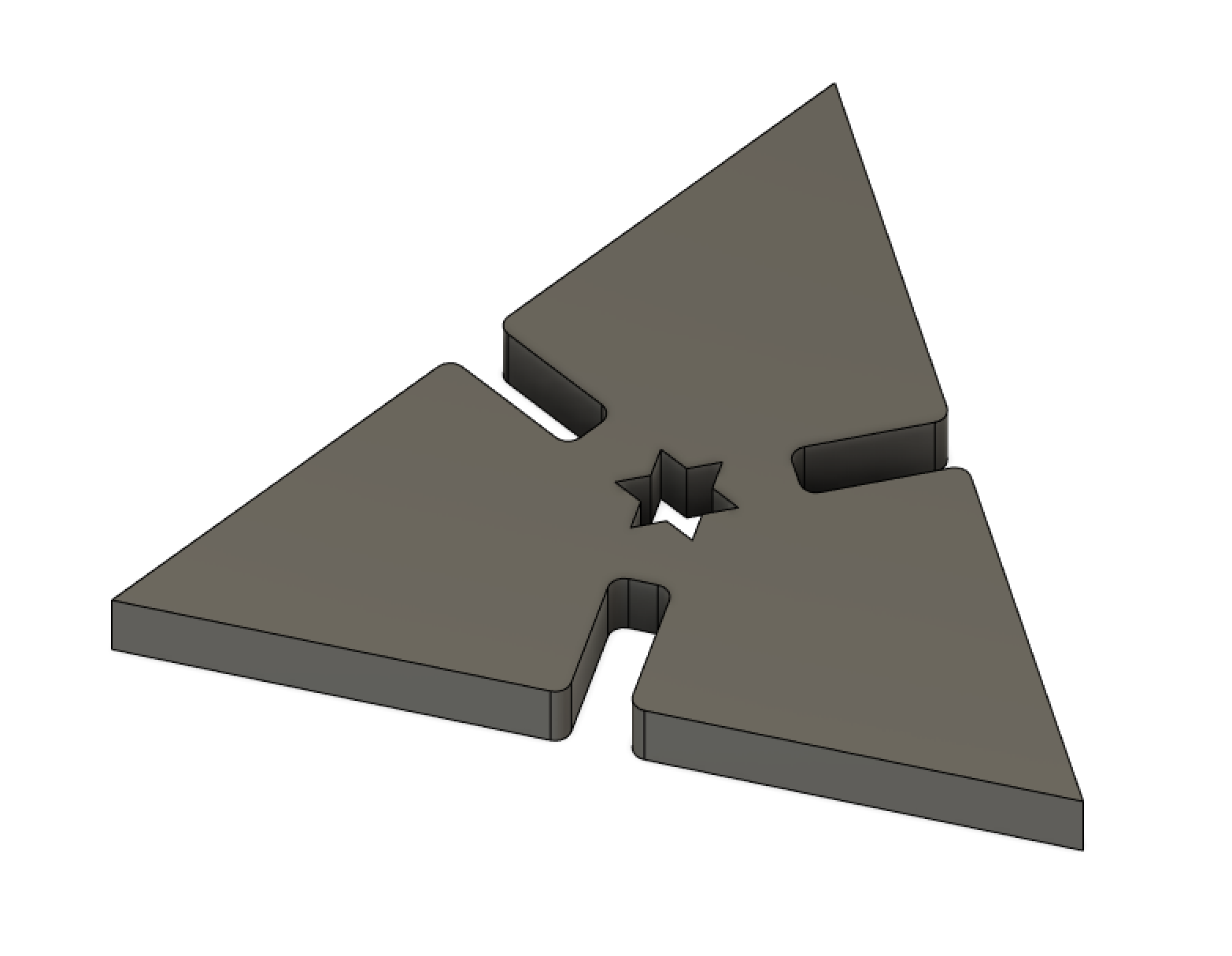
I ended up going with a triangle design with a fun-shaped hole in the center, giving myself some angle control with how i attach hexagons and triangles. Now that I have a basic press-fit design going, I still want to try and construct my original design. Even if I can't laser cut the exact slits that I want for my angled joint, I can still cut out the different wall pieces and glue or hand cut the notches.
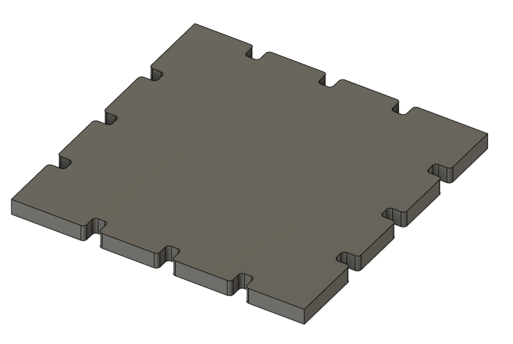
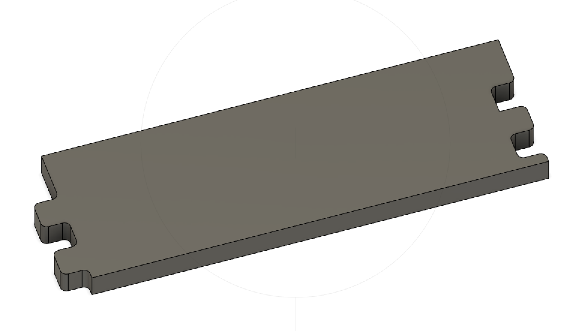
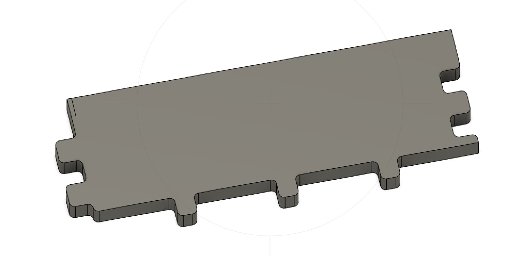
With my hopes and dreams restored, I finished constructing the wall pieces from my original sketch, although instead of the two different types of wall pieces from the drawing, I had all of the side notches mimic the base wall pieces so I only had to construct one type of wall. My finished wall pieces look like this:
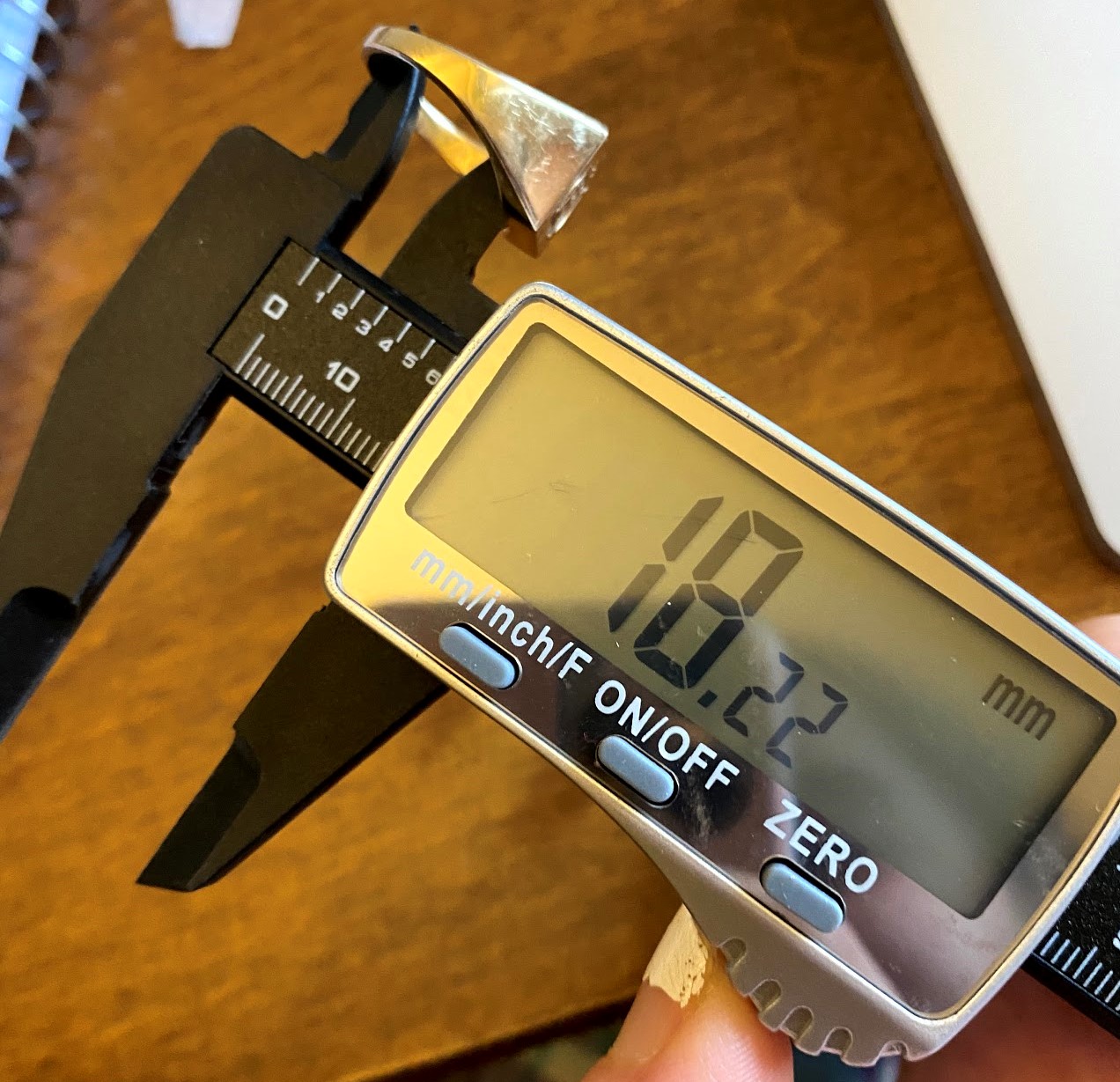
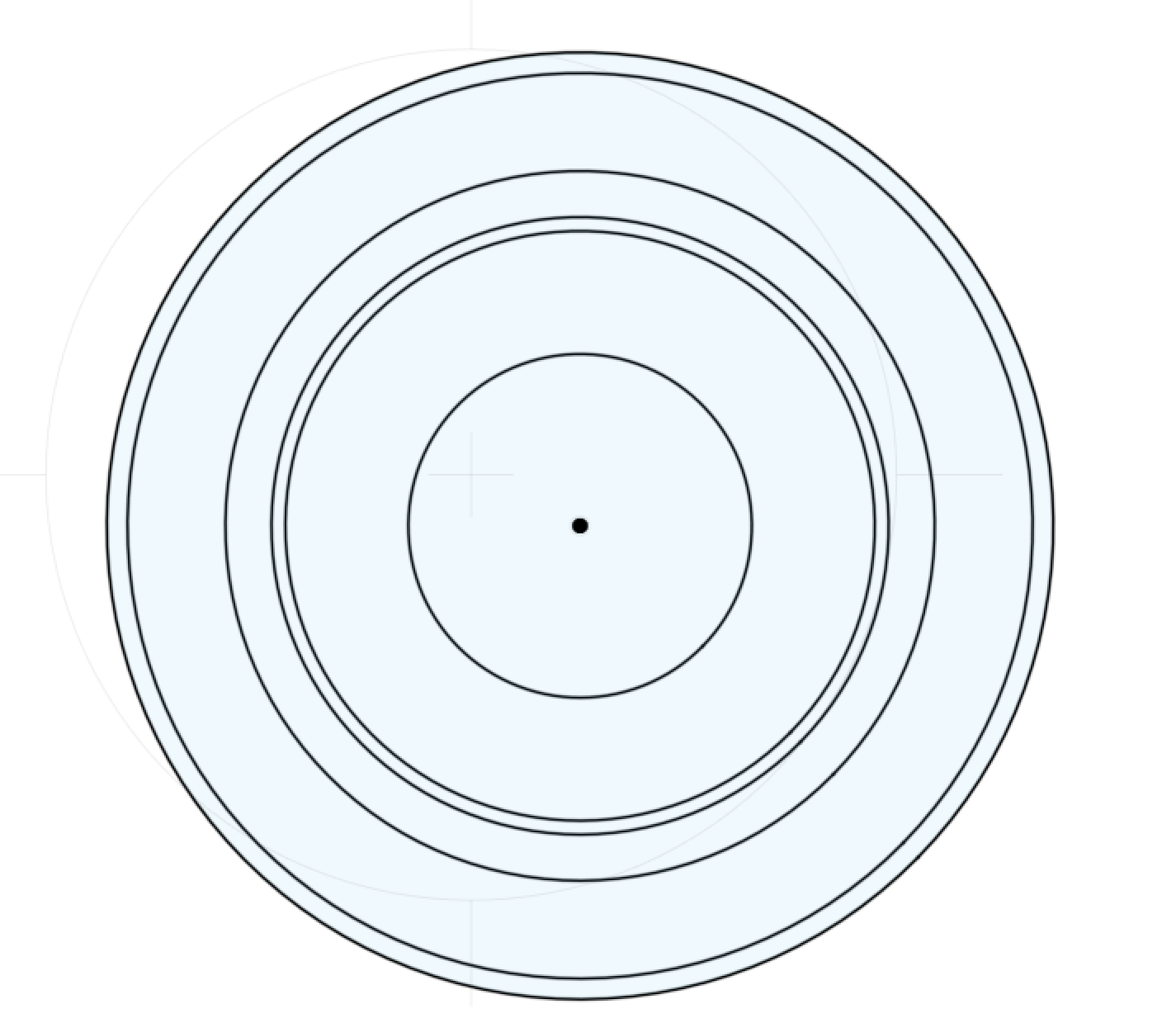
Now, we wait for the printing process on sunday. In the meantime, let's start 3D modeling some objects around my dorm. Rather than model kit parts, in class we discovered that we could model anything we wanted from around our houses. For my first object, I went with my favorite ring, because I think it has a really cool shape to it. I started with a circle, whose diameter matched the inside diameter of my ring. I measured every length and diameter that I needed with the caliper in the picture.
Using the circle I had just measured, I sketched the midplane geometry of the ring and extruded the band on either side. Next, I extruded the center panel and the two flat joints connecting the band and the panel to get the pre-tapered ring shape that you can see in this image. Up to this point, the process had been quite straightforward. I hadn't yet had to deal with any mismatched geomertry from the midpoint to the end, making this part quite fast. I felt very unstoppable.
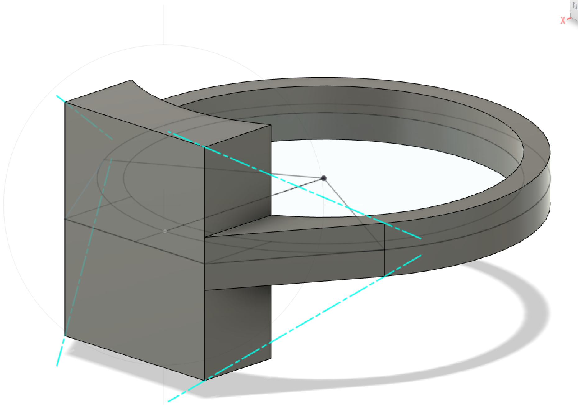
All I had left were a few connective tapers. That shouldn't take too long...right? Well, unfortunately my hubris caught up with me, and I ended up spending a few hours working on these final pesky tapers. First, I overfilled all of the four taper spaces to get the big hunk of rock attached to my tiny band. Now, I had to figure out how to delete the parts that I didn't want from this chunk.
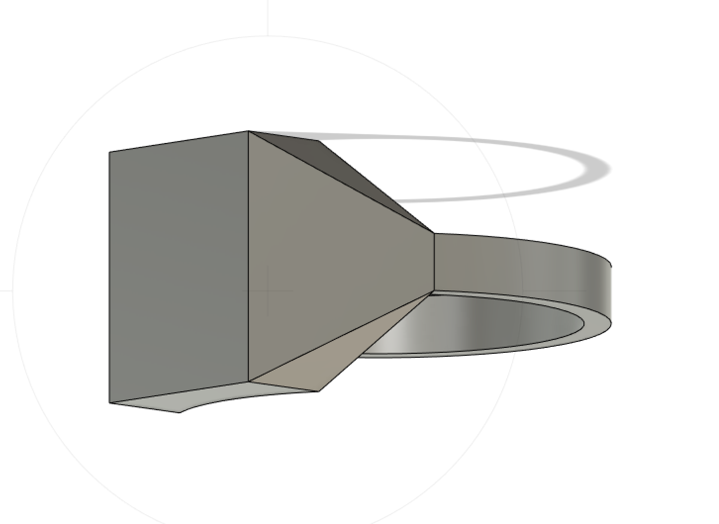
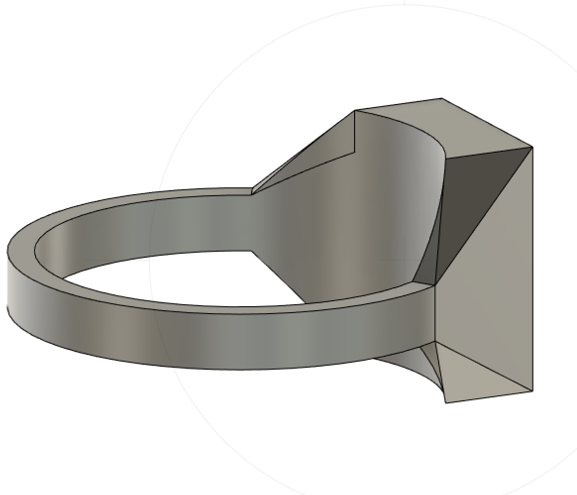
First, I had to separate each of my tapering zones from the rest of the body of the ring, so that when I cut the taper zone I don't also cut into the band of the ring. Each of the four tapering zones has six corner points to work with, and I could construct as many planes as I wanted with any combination of three of those points. I ended up watching a tutorial to learn how to construct these planes and cut things out, which turned out to be extremely helpful. To get the right cuts, I first had to make two planes connecting the base of the taper with each of the top points respectively so I could have a smooth transition from the band to the taper. This alone wasn't enough, the taper connected with the top of the face too early. To fix this, I made a plane connecting the top two surfaces with the inner bottom corner point to cut off the extra long ring face and to start the taper at the true edge of the face. Making these three cuts in each taper zone made a ring shape I was finally happy with.
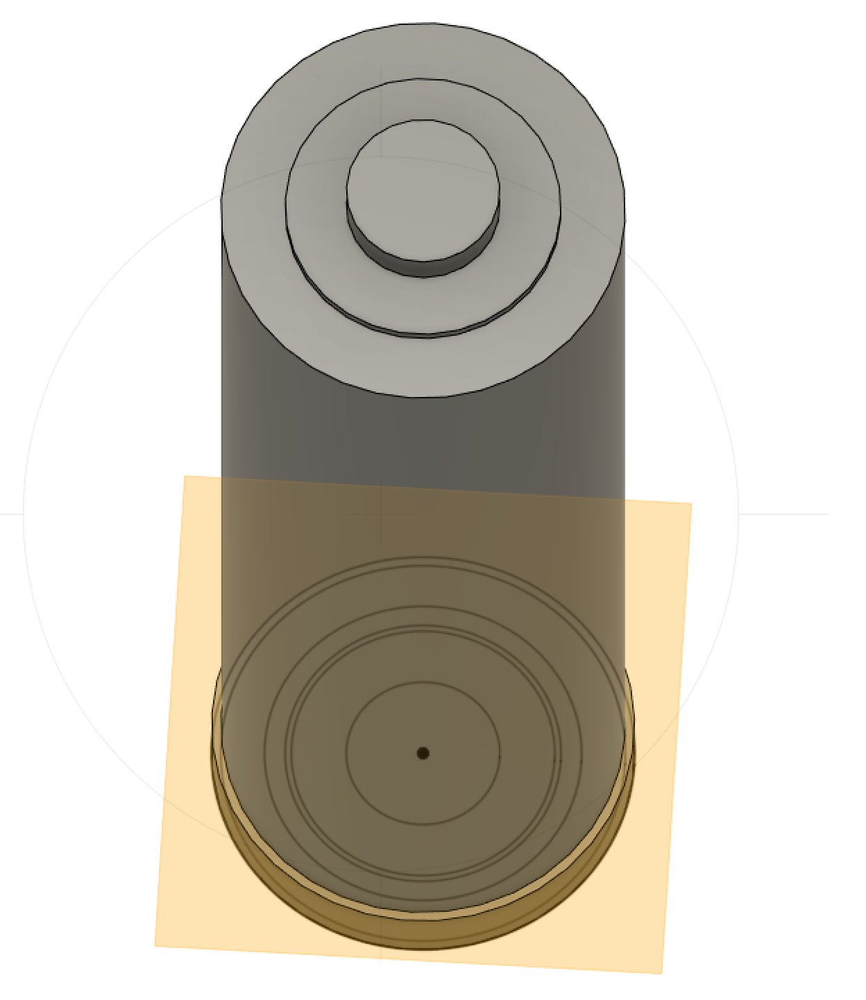
Okay. Only one more object to model. After spending four hours on my ring, I figured I should go for something a bit kinder. I also noticed that the batteries in our kit are quite nicely designed: they are cyllindrical. Excellent. They weren't completely straightforward--I still had to add the indents for the positive and negative charge, and I had to get the ridge at the base... well. Maybe this won't be as simple as I initially guessed.
In my initial 2D sketch, I wanted to include as many of the unique diameters that I would have to incorporate later on to minimize the headache as I continue. Then, I measured the height of the inner plus charge piece along with the rest of the battery to get the cyllinder's height. I also subtracted 0.6 mm from this measurement, as that is what I measured the difference in height to be between the metallic negative pole and the wrapped bottom of the battery. I subtracted this amount so I could add it back as negative value below my initial sketch. With this base in place, I could add the cyllindrical pieces for the positive end below the bracket and the next slight indent before the wrapping.
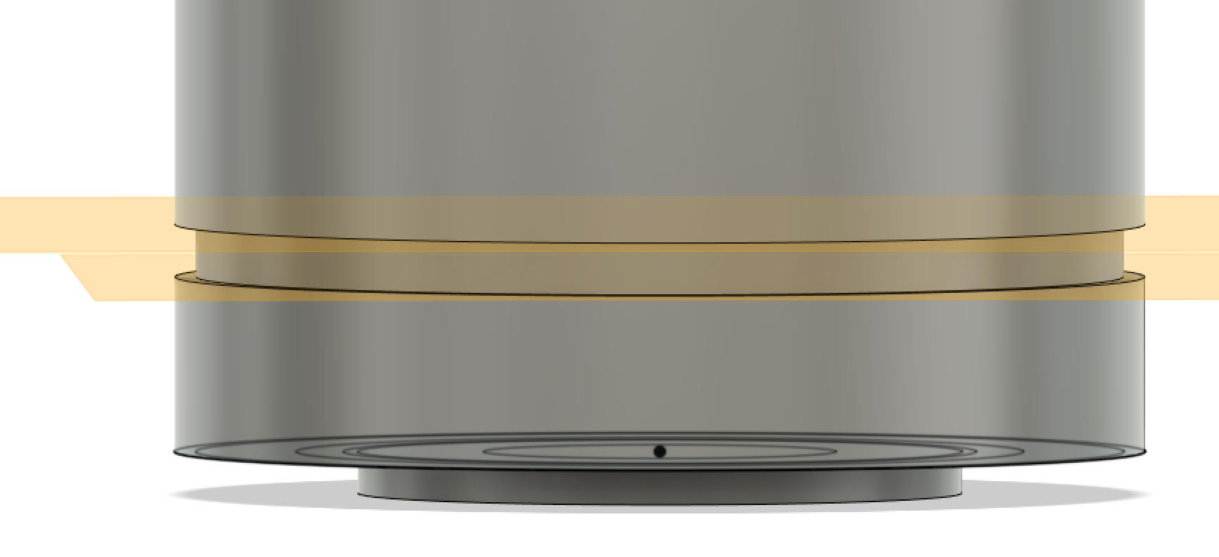
Next, I had to figure out how to add that notch into the bottom part of the battery. I made the whole battery as wide as the interior of the notch. Then, I added 2.5 mm of wider base before the notch.Now I have to work on the notch. To do this, I first put a plane where my base ended so I could come cut out the notch later. Then, I stacked the height of the notch on top of the plane. I then put another plane at the top of my notch before constructing the rest of the battery on top of it. Now I have to make the cuts. I split the body of my battery first at the upper plane. I then split that bottom portion with the outer ring so I could isolate the notch fill. I then chopped off the base of the notch, leaving the fill of the notch behind that I could remove.
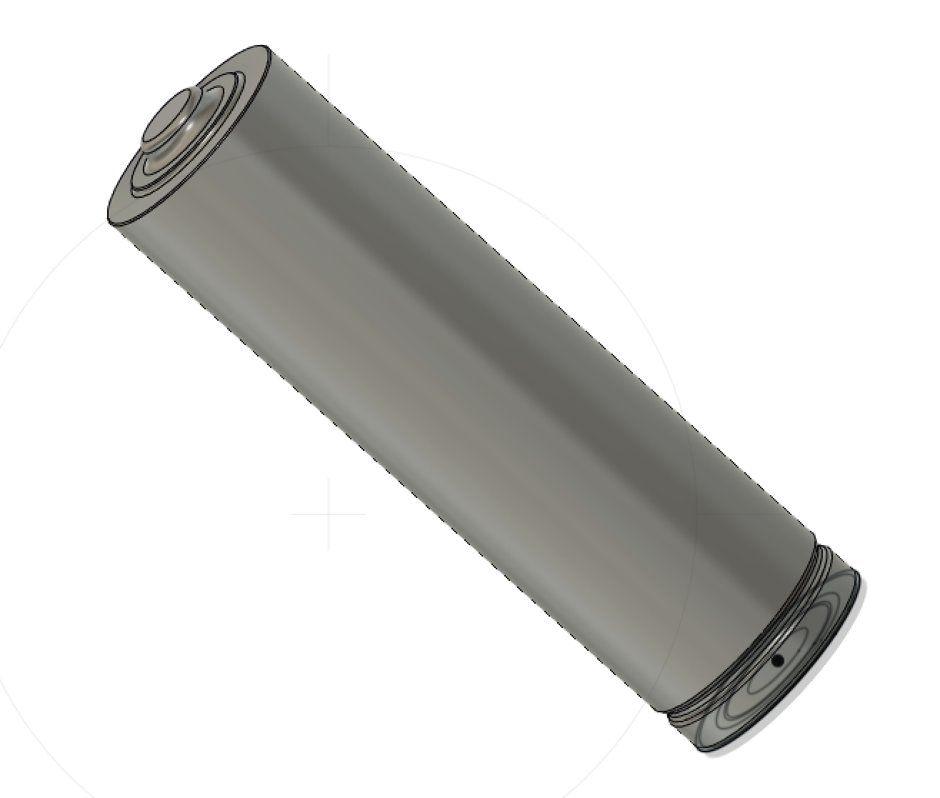
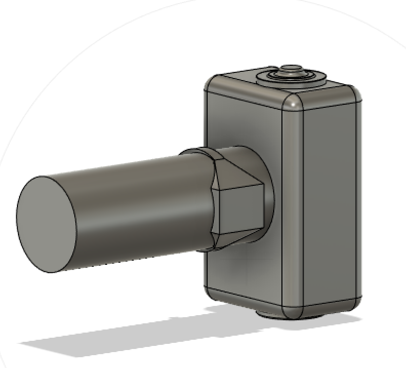
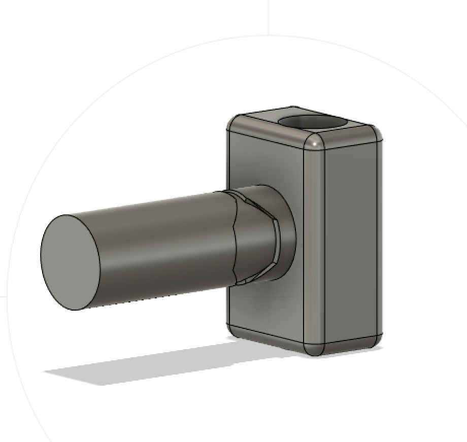
Now, for the finishing touches. I selected all of my sharp edges and added fillet to round them out like the battery. I played with different fillet radii for each segment to get a shape I was happy with. This is the final product. I think it looks really good! Now, I'm supposed to construct an assembly for my objects. While an assembly for my ring and the battery seems a bit strange, I'll still build a custom casing for it. I first built a box with filleted edges that would allow the edges of the battery to stick out for use. All I had to do was sketch and extrude the box before deleting the volume of the battery by splitting and removing the battery space. I then built an attached ring holder on the top of the casing, with a custom indent to hold the ring in place. This also wasn't too bad. All I had to do was construct a cyllinder and delete the space where the ring would sit. My final product is below!
© Lauren Cooke 2021