Final Project: 3D Drawing
Motivations
After a few weeks of class, I finally decided that I wanted to explore more applications of foil capacitance sensors. These plates measure capacitance. Essentially, the closer an object gets to the plate, the greater the current that a sensor reads. I also really like to draw, despite not being the best at it, making representing 3D objects on a piece of paper extremely difficult. So, I figured why not design a device to render my 3D mid-air sketches as a 2D picture? This way I could map coordinates to the changes in capacitance when I waved my hand over some plates, not to mention that it is a really fun way to actually produce what seems like sorcery with midair hand motions actually being represented on a computer screen. With this thought in mind, I could finally begin designing and building.
In reasearching for this project, I came upon a make tutorial for a 3D capacitance sensor linked below:
Ultimately though, besides the physical cube structure, I had to abandon the tutorial and build the circuit and write my code based on what I had learned in lab and previous experience. Let's get started!
What is Capacitance?
In this project, capacitance, or the ability of a circuit to store energy, was crucial to allowing my hand to draw shapes in the air. The circuit that I built uses the capacitiveTouch library's capacitor design so that I could use the library in the code. Essentially, we send charge to a foil plate over a strong resistor via a send port on our microcontroller, while a resistor-less wire connected to a different arduino report recieves the signal. By timing how long it takes for the recieve wire to reach the built up charge of our sent signal, we can measure how close an object like my hand is to the foil plate. With this design, the closer that I put my hand to the foil, the longer that time would take as my hand absorbed more energy. You can check out the library and its description of the circuit for yourself in the link below.
Now that we have a better understanding of how capacitance works, we can proceed with our build.
Materials
1 8 in. x 8 in. cardboard box
3 7.75 in. x 7.75 in. smooth aluminum foil sheets
1 roll of electrical tape
3 dual-ended alligator clip wires
1 breadboard
7 pieces of wire
3 10 Mega ohm resistors
1 Metro M0 Express and cable
The Build
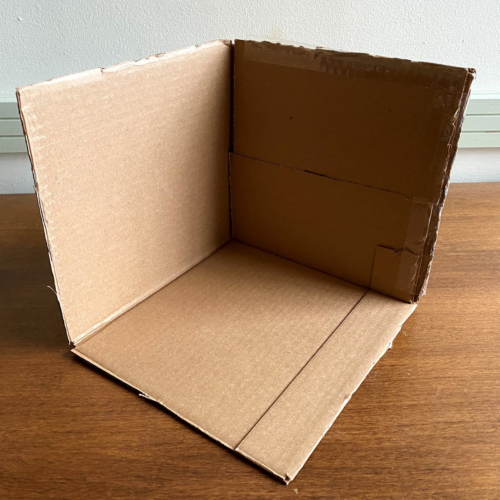
1. cut the cardboard box at its edges so that three faces of the box are still connected at a corner. This cardboard will be the frame for your capacitance sensors.
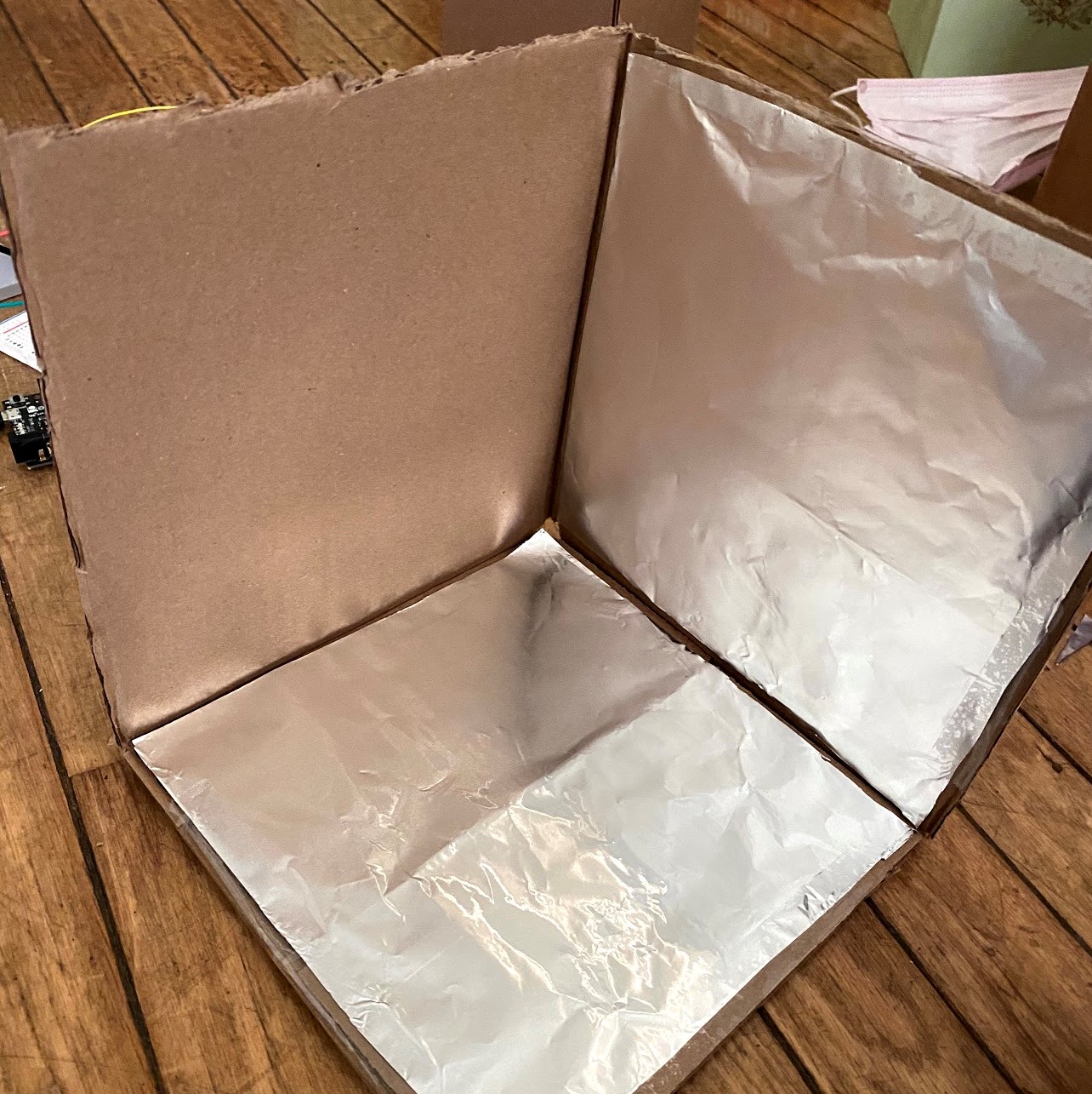
2. take your foil sheets and tape them centered on each interior cardboard wall. For now, only tape the outer edges to leave yourself room to add circuitry later on.
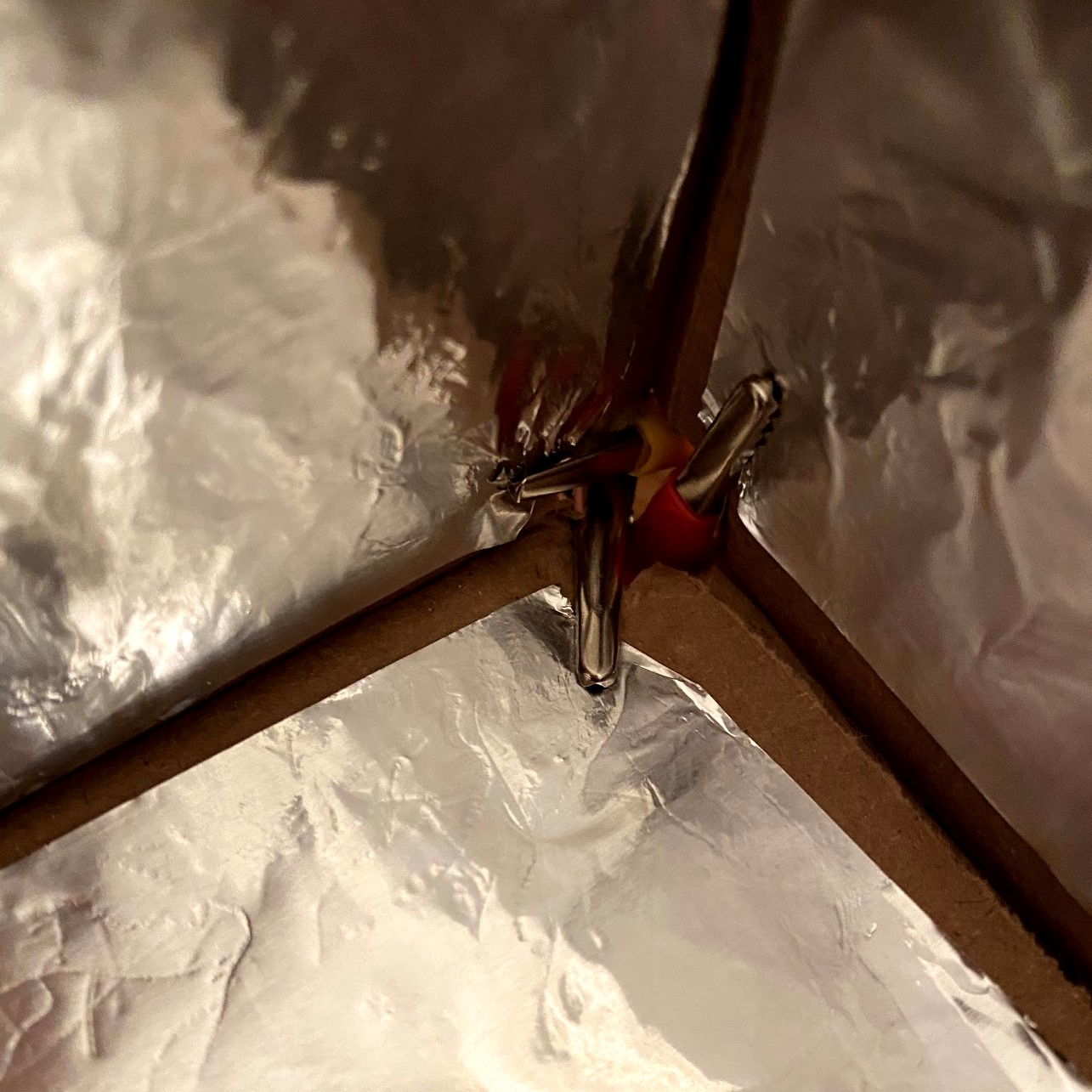
3. attach your alligator clips to each sheet of foil and tape everything in place. When doing this, be sure that each foil does not touch another by taping the inner edges with electrical tape.
The Electronics
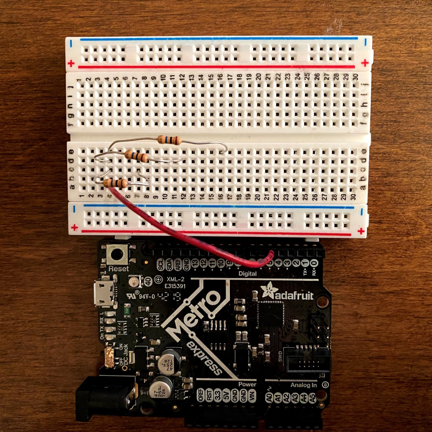
4. Connect digital pin 5 of your Metro M0 to a row of your breadboard. This wire will send your output voltage to each sensor. For each of your three resistors, connect the gold-striped end to the row with your previous wire, and connect the other end to its own row of the breadboard. Be sure that the wires on your resistors don't touch each other!
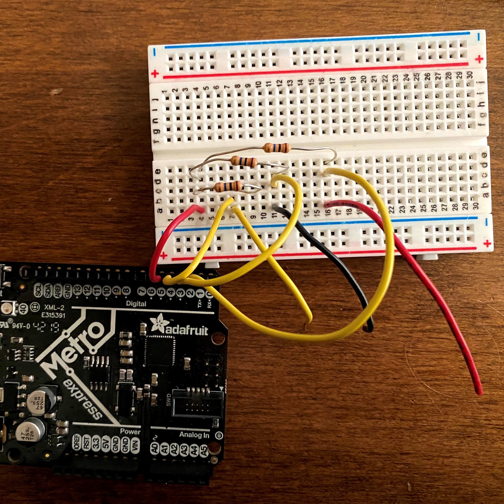
5. Place two wires into the breadboard at each new row that a resistor touches, for a total of six added wire pieces. Resistor 1 (R1) will have one wire connecting to digital pin 2 of your metro, resistor 2 (R2) will have one wire connecting to digiral pin 3, and resistor 3 (R3) will have one wire connecting to digital pin 4.
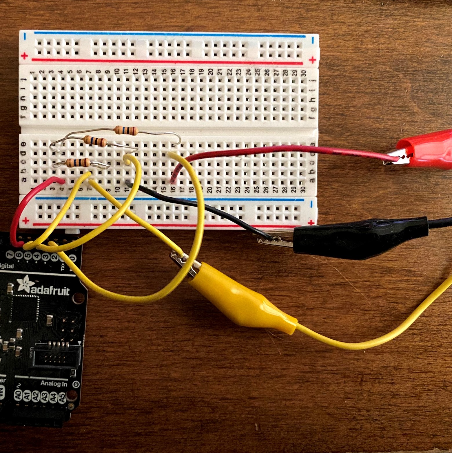
6. With the three remaining wires, R1's wire should connect to the plate that will be your y axis, R2's wire should connect to the plate that will be your x axis, and R3's wire should connect to the plate that will be your z axis. Use the corresponding alligator clips to attach. To avoid intereference, use electrical tape to wrap each clip and its wire together.
The Code
7. Matching our pins from the building section, we can write a program in arduino to read each sensor's value as a 3D point in serial. I defined the Metro M0 pin numbers I used at the top so you can modify the values to match your setup.
#include <CapacitiveSensor.h>

//ports
 const int xPlate = 3;
 const int yPlate = 2;
 const int zPlate = 4;
 const int receive = 5;

//sensor definitions
CapacitiveSensor x = CapacitiveSensor(receive, xPlate);
CapacitiveSensor y = CapacitiveSensor(receive, yPlate);
CapacitiveSensor z = CapacitiveSensor(receive, zPlate);

void setup() {
  Serial.begin(115200);
}

void loop() {
  long sensorValueX = x.capacitiveSensor(1000);
  long sensorValueY = y.capacitiveSensor(1000);
  long sensorValueZ = z.capacitiveSensor(1000);
  String printer = "(" + String(sensorValueX)+ ", " +
                   String(sensorValueY)+ ", " +
                   String(sensorValueZ)+ ")";
  Serial.println(printer);
}
8. Now, we can write a python script to read this serial data and convert it into a graph. One advantage of using python is that matplotlib will autoscale every axis, meaning we can simply use our raw coordinate information.
import serial
import numpy as np
import matplotlib.pyplot as plt

fig = plt.figure()
ax = plt.axes(projection='3d')

ser = serial.Serial('COM5') #replace 'COM5' with your own serial address
ser.flushInput()

#storage arrays
x = []
y = []
z = []

#clean serial data and add point information to respective storage arrays
try:
    while True:
        ser_bytes = ser.readline()
        decoded_bytes = ser_bytes[0:len(ser_bytes)-2].decode("utf-8")
        clean_point = decoded_bytes.replace(" ", "")
        cleaner_point = clean_point.strip("()")
        vals = cleaner_point.split(",")
        x.append(float(vals[0]))
        y.append(float(vals[1]))
        z.append(float(vals[2]))
        print(decoded_bytes)
        # break infinite data read with Ctrl+c keypress
except KeyboardInterrupt:
    print("Keyboard Interrupt")
    pass

# convert storage arrays into numpy arrays
r = np.array(x)
s = np.array(y)
t = np.array(z)

# label axes
ax.set_xlabel("x axis")
ax.set_ylabel("y axis")
ax.set_zlabel("z axis")

# plot points and connecting lines before showing us
ax.scatter3D(r, s, zs=t, c=t, cmap='Greens')
ax.plot3D(r, s, z)
plt.show()
Beware of some common python errors with the code. First, the program will read your data until you type Ctrl-C into the console that the program is operating in, so if you cannot make the program stop while running it, be sure that you have your program running in a terminal environment! Also, be sure to modify the serial port that you are reading from based on your computer (replacing "COM5").
Finally, upload your arduino script to your metro M0 and run your python script with the board online. Your very own 3D drawing machine is ready!
Final Thoughts
Overall, I am pretty satisfied with my final product. I learned so much in designing both the code and the circuitry from scratch, and I definitely feel a lot more confident in my abilities because of it. I look forward to continuing to grow in the makerspace over the next three years!