Electronic Input Devices
This week, we learned about and calibrated both a capacitve sensor and another sensor of our choosing to become familiar with electronic input devices. For my sensors, I decided to build a pressure sensor and to see what I could do with a hall sensor.
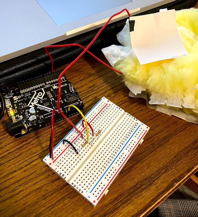
For my capacitive sensor, I built a circuit just like the one from lab on thursday. I dug around my room and found a swiffer duster pad, and I put that between my two electrodes. I then had to calibrate my sensors by adding a standard unit of weight to the pressure plate and recording the change in values that I found as I added more and more weight. Doing this, I could construct a calibration curve of these weights and the sensor values I recorded. For my standard weight, as I do not have access to any sort of scale, I used Duracell AA batteries. Axes are labled in the graph below.
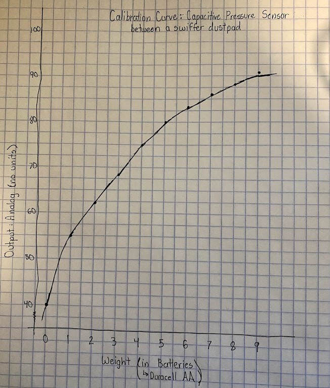
The graph reflected the change in height of the swiffer pad as I added more weight. Initially, the pad would shrink significantly with the addition of a single weight, causing more significant change in my sensor values. However, as the number of weights on the pad increased, adding a single weight did little to shrink the pad, and therefore did little to change the sensor value. After building this calibration curve, I've realized that, although squishier, the swiffer pads don't really carry charge well. This sensor should have a range from 10 to 1000, so this medium limiting that curve to only hit values between 40 and 100 is quite small. Using the results of this first calibration attempt, I could better calibrate my next sensor.
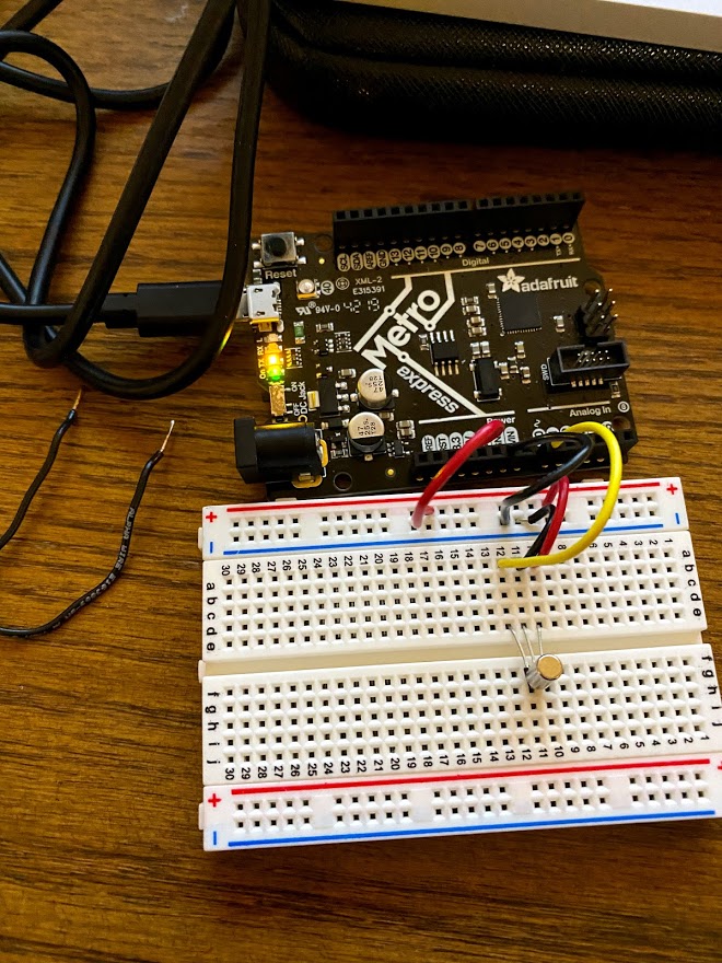
For my other sensor, I choise to calibrate a hall sensor. This sensor detects magnetism quite accurately, so I thought it would be interesting to calibrate it and try implementing it into something! First, I hooked the sensor up to a simple calibration circuit and wrote some code to spit out the sensor reading every 150 microseconds. This sensor has an added layer for calibration, where my magnet pictured on top of the sensor will bring the sensor value either down to 10 or up to 1000 from the standard 500 value depending on which side of the magnet is exposed to the sensor. For calibration purposes, I decided to only calibrate for the bottom half of my range, as the graph for the upper half would be a mirror image of the lower half.
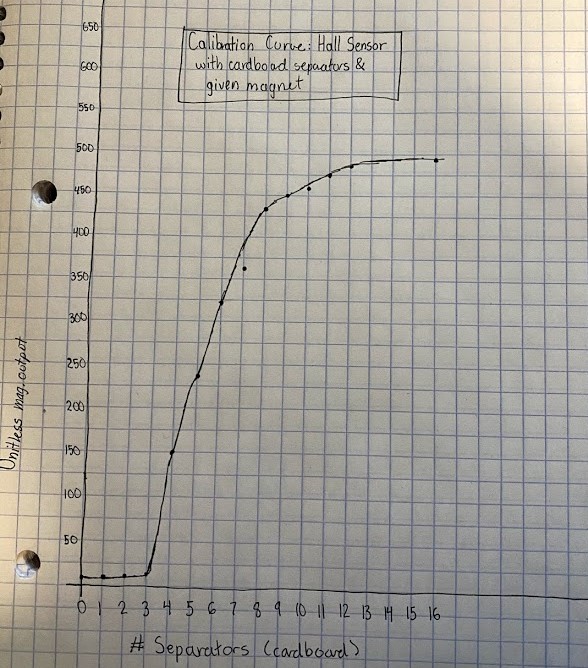
To calibrate this sensor, I cut out a bunch of cardboard squares and stacked them on top of each other to create uniform spacers to separate the magnet from the sensor. I then recorded the value of the sensor output at each spacer distance until adding more spacers failed to change the sensor value. With this sensor, I found that adding distance didn't make much of a difference until hitting a critical distance, at which point sensor values began to change significantly. From there, adding distance became less and less impactful until hitting 16 spacers, at which point the sensor values stopped changing more than the built in margin of errror of the sensor.
Using this calibration curve of my hall sensor, I decided I wanted to try and use it to build a theremin. Basically, I would hook my sensor to a circuit alongside a buzzer, and I would use my calibration data to map the sensor values I recorded to a pitch for the buzzer play. In theory, as I moved my magnet closer or further from the sensor, the pitch would change. I hope you enjoy the results!
void setup() {
  Serial.begin(9600);
}

void loop() {
   int sensorValue = analogRead(A0);
   int pitch = map(sensorValue, 10, 500, 1000, 1800);
   Serial.println(sensorValue);
   delayMicroseconds(500);
  tone(9, pitch);
}