Machine Building and End Effectors
This week, we learned all about stepper motors and how to build simple machines. I wanted to start mapping 2D coordinates, building towards my final project. I also tried my hand at capacitance mapping, but I ended up having some problems with my cube design that I wanted to spend more time on next week.
First, in lab I followed the tutorial to build a single linear carriage system that depended on a stepper motor. I spent a lot of time with sandpaper and pliers removing 3D printer supports and sanding the edges of the plywood parts on the carriage, focusing on the outer edges of the wood where I would be touching the machine and on the pieces where multiple parts would have to slide on each other to try and minimize resistance. I then wired and coded this carriage using the tutorial from Tuesday's lab, and I ended up getting the machine to work after a few hours!
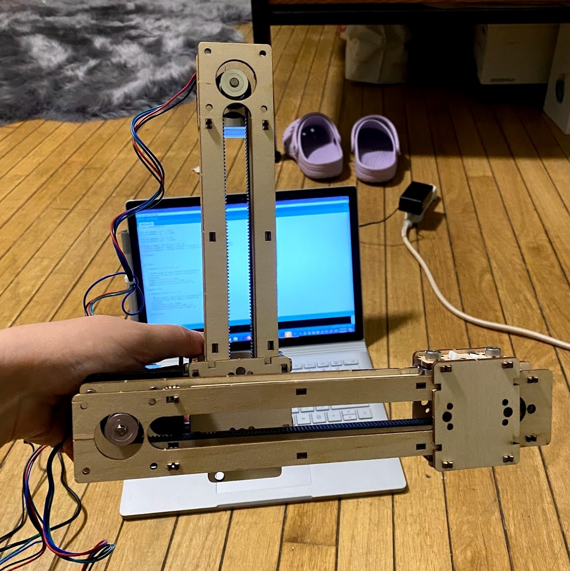
After building one carriage to traverse one axis, I duplicated the process for a second carriage, only to realize later that I would have to take one of them apart to attach an angle bracket to the stepper motor base. I realized then that it would have been quite useful to sketch out my design idea before throwing parts together, but I suppose a lesson like this one really sticks when you have to suffer the consequences. As if that wasn't bad enough, the bolts we used to hold the bearings in place on the carriages would not fit through these brackets, so I had to come up with another way to attach the two pieces.
I dug through the kit and I found these thin yet surprisingly long bolts and some washers. Using the washers around the bolt head to widen the base so it would not fall through the bracket, I attached the wood piece to the angle bracket using four of these screws. I also had the foresight to insert the bearing bolts into the wood piece before attaching it to the bracket, meaning I could throw on a washer and the bearing before sealing everything with some nuts.
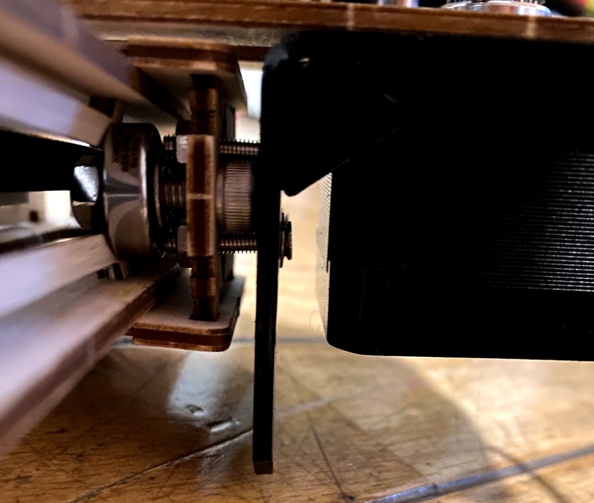
One flaw in this design was the excess width it added to the carriage. The excess length on thin bolts from the kit pushed the bearing further away from the wood, meaning the press-fit wooden pieces would barely fit into place. I ultimately ended up taking the top piece of the carriage off to relieve the immense amount of stress on those wooden pieces to stay in place, allowing the carriage to slide with much more ease. To fix this problem, I would either re-cut the outermost pieces of the carriage to accomodate this new width or find a slightly thinner bolt that would both fit through the bracket and secure the bearings.
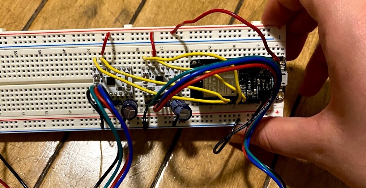
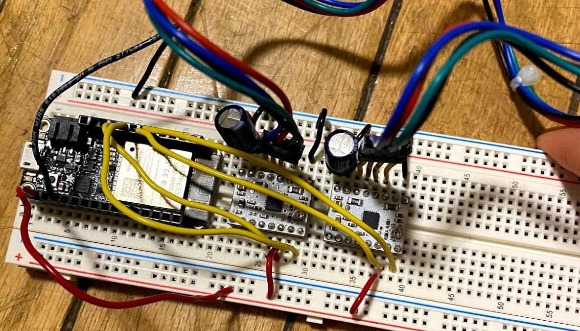
To accomodate two carriages, I was going to need a bigger breadboard and double the wires. I ended up duplicating the stepper motor control setup from the tutorial, combining the power fed to the motors and the motor drivers in a single circuit on a single board. Because I was using the Huzzah, I ended up refering to a pinout from the product website to find two pins that I could use to control the second stepper motor. Now, all I had to do when writing code for my double carriage was to write up the pin information and setup two separate stepper objects so I could modify each one individually.
I decided to make the grid travel diagonally between two opposing corners on an infinite loop, but finding the correct values to feed into the position function turned out to be a bit harder than I thought. Throughout this process, my tests depended on manual calibration, meaning I had to move my carriages back to the origin point after each test while the motors were disengaged. But, I found that whenever I went to rewrite the Huzzah board, the previous program would continue to run, meaning my manual calibration would get undone and I would have to quickly unplug the board after uploading and before execution. Because of this calibration problme, writing a self-contained looping program turned out to be a strategic design choice, as each movement undid the previous movement and prevented any damage from occuring.
#include <AccelStepper.h>

const int stepPinx = 13;  // blue
const int dirPinx = 12;   // orange

const int stepPiny = 27;  // blue
const int dirPiny = 33;   // orange

// Define a stepper and the pins it will use
AccelStepper stepperx(1, stepPinx, dirPinx);
AccelStepper steppery(1, stepPiny, dirPiny);

void setup()
{
}

void loop()
{

  if (steppery.distanceToGo() == 0 && stepperx.distanceToGo() == 0)
  {
    // Random change to speed, position and acceleration
    // Make sure we dont get 0 speed or accelerations
    delay(1000);
    steppery.moveTo(1000);
    steppery.setMaxSpeed(500);
    steppery.setAcceleration(500);

    delay(1000);
    stepperx.moveTo(1000);
    stepperx.setMaxSpeed(500);
    stepperx.setAcceleration(500);
  }
  steppery.run();
  stepperx.run();

  if (steppery.distanceToGo() == 0 && stepperx.distanceToGo() == 0)
  {
    // Random change to speed, position and acceleration
    // Make sure we dont get 0 speed or accelerations
    delay(1000);
    steppery.moveTo(-1000);
    steppery.setMaxSpeed(500);
    steppery.setAcceleration(500);

    delay(1000);
    stepperx.moveTo(-1000);
    stepperx.setMaxSpeed(500);
    stepperx.setAcceleration(500);
  }
  steppery.run();
  stepperx.run();
}
And there you have it! I am really excited that I got this 2D system to work, but I wanted to do a lot more, especially surrounding capacitance, than I ended up being able to do. Because this mapping idea is so central to my project I plan on using this system that I've build to tangibly test my progress with the capacitance mapping, and I am in the works of assembling a small prototype using the smooth copper plates and their storage paper from the kit. I am excited to incorporate that in the future and I am proud of what I accomplished this week!